
Hello and welcome to my blog! In this post I will detail the process of creating a live edge shelf to be wall mounted. Those of you who have followed along with my blog may recall a very similar build recently. For this build I will be making the steel mounting bracket for the build in addition to the woodwork, so I focus the attention on that aspect of the build more so than focusing very specifically on the woodwork.
This project started off with the client accompanying me to my local supplier of wood slabs where we shuffled through them until stumbling upon a slab of walnut that fit the bill. When hunting for slabs we had some requirements of the slab that we needed to maintain. Our requirements were that of a slab on the shorter side with good character that did not have a great depth to it. The shelf I would be replacing was a simple wall mounted board of veneered MDF that was about 8″ deep. My client wanted for something a little more exciting in replacing that shelf and I was happy to accommodate that request.

Next I determined exactly how deep to make the slab and where to position the line to make the initial cut. I needed to rip the slab down to a reasonable depth and create a reference edge.

I had a feeling that this slab would offer quite a challenge, being curved as it were I expected it would also be twisted. I was not disappointed, it had plenty of twist. Luckily my client was also looking for this piece to be significantly thinner than where it stood originally. It required a 3/8″ thick shim at each corner to level it out.

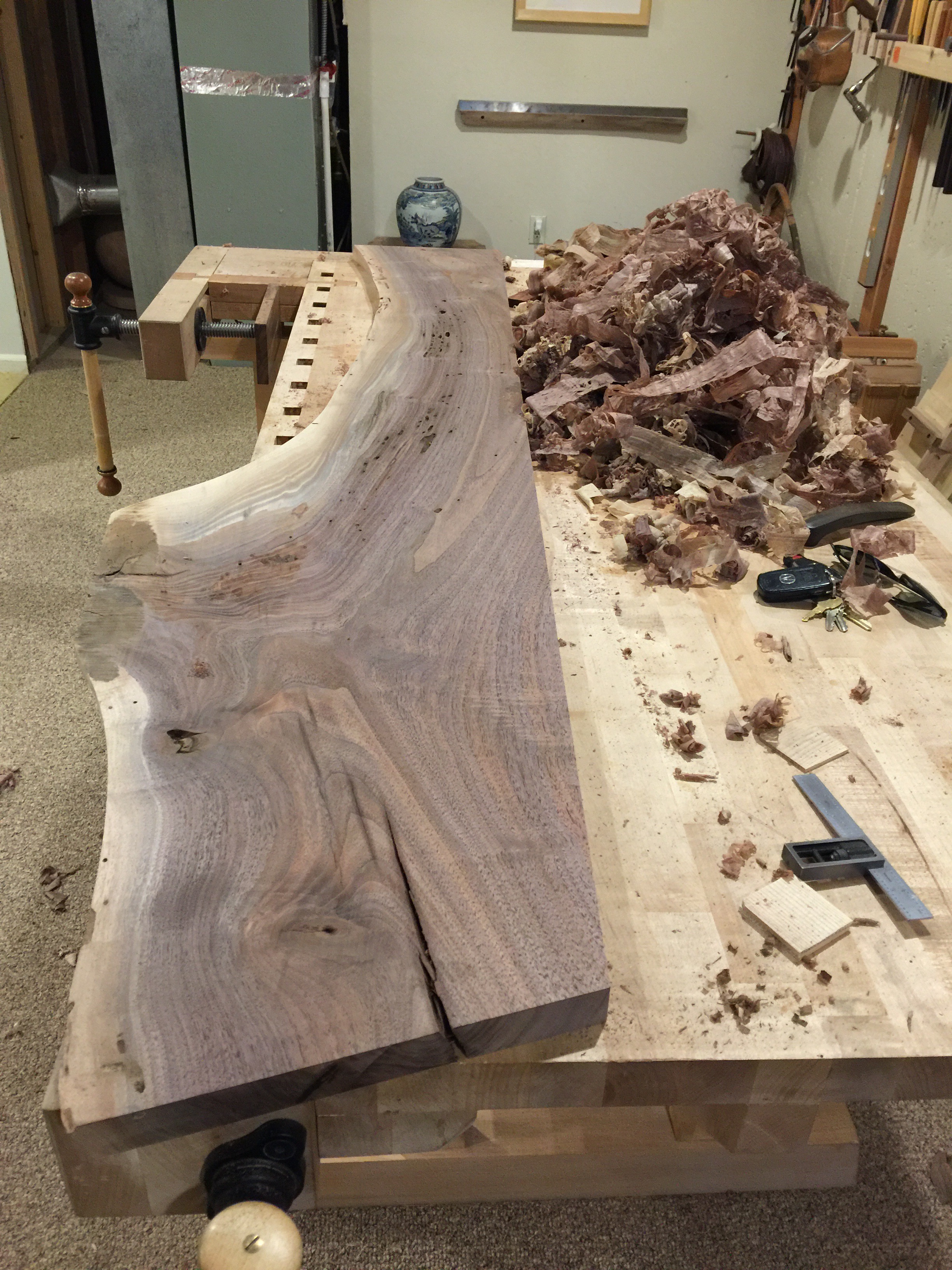
I began jointing the slab first by jack plane, followed by try plane working to remove the twist and create a flat reference face.

One area of the reference face remained significantly lower than the rest of the face. I decided rather than continue to remove material beyond the near 7/16″ I had removed from each corner, that I would instead taper the face toward that low spot to remove the roughness.
If ever my readers should find themselves in need of a unique exercise program, might I suggest removing heavy amounts of wood from a figured slab.

At this point I had my work cut out for me, with the reference face now created I could see that I would need to take nearly 1/2″ off of the opposing face to bring it to the lowest point. Then I would need to remove additional material from this face to keep it from twisting again. Rather than do this by hand I decided such a bulk of material would need to be done by thickness planer.

After thickness planing was completed I returned to hand planing. The remainder of my work was to finish plane both sides of the slab. The slab, being at eye level would be viewed top and bottom and so both areas needed to be detailed to a fine finish.
Removing such a large amount of material always risks unleashing other stress in the remaining material causing it to again twist. However this slab remained flat and continues to remain flat. I verified this both after finish planing and again later on.
Next to repair the split forming at the end of the slab. This is done with a very recognizable joint referred to commonly as either a dutchman or as a butterfly joint. These joints are not cut the full way through the slab, as is commonly misunderstood, but only about 1/4″-3/8″ into the slab. This slab is visible from the underside and so an additional pair of dutchmen were made for the underside and also installed.
The dutchmen are best cut from quarter or rift sawn material to ensure that they’re free of grain runout.
The dutchmen are then set into place, after which I use a knife to trace around the dutchman followed by cutting the waste out. The final steps are to chop to the knife line, then seat the joint in place. Ideally the dutchmen should install tightly, in fact I will typically taper the sides of the key to ensure that it becomes tighter as it seats. The strength of this joint is not solely mechanical, but also a large long grain glue surface, so it is important that the key actually seats in the joint.

Once the glue set, I planed the joints flush.

The process was repeated on the backside of the slab, along with a large square patch to repair a big knot. Some knots can be retained, but if they’re very loose and the grain around them also loose then they should be removed and the area patched.
I continued my work by detailed the edge of the slab. I continuously debate how I will approach this area of the work and most commonly I will work the sides to a finish with a spokeshave. In this case, being that the slab had a large curve to it, I decided to detail the area with a spoon bottom plane. The spoon bottom plane, or shi-ho-sori-ganna, creates a light texture that I feel compliments the natural edge.

The top of the edge was then detailed with the mentori-ganna.

The slab is now detailed, less the ends, and my next step is to begin creating a support system which will allow the slab to be wall mounted. I decided to use a system of battens under the slab, dovetailed in. The battens would be bored to receive steel support rods then welded to a wall mount. This bracket could then be attached to the wall and the shelf installed onto it. This presented quite a challenge in that all of these parts had to be created with precision in order for this bracket to work. The first step begins with splitting the battens out to ensure that they’re straight grained.

The battens were then shaped and cut into the slab. I admit to being highly caught up in that work and it slipped my mind to photograph the process. In any case, I did so recently in a series entitled Live Edge Tsuridana.
I purchased chrome moly round bar to make the mounts. I did not need the strength of chrome moly, but instead the precision in it’s cold rolled form. The spec’d size was 3/4″ and the provided material measured to be within .005″. I cut the rods down to size, then detailed the cuts filing them by hand.

Next I removed the battens from the slab, setting them in the milling machine and boring the long holes required to receive the chrome moly rods. This proved rather difficult, first I had to find an appropriate bit. I’ll spare my readers of the details of that process but I landed on a bormax bit and extension. Bit extensions can be troubling, but the extension in this case was highly precision. The bit also provided with it a helpful guide on suggested bit speeds. The bridgeport mill makes good use of that type of information, having a easily adjustable quill speed.
Boring holes over 6″ deep with a machine, in this case, requires one to carefully adjust the depth of the bit, quill and bed in order to allow enough room at each point to make cuts and clear chips.

Next step was to create the mounting plate which would connect the wall to the wooden slab. The mount needed to be strong in place, but reasonable flexible outside of that. I chose heavy 300 series (316 IIRC) stainless plate and punched holes into it using a 36 ton metal working machine known as an Ironworker. It punches holes, shears plate and angle iron, and notches, a really handy thing to have when dealing with stainless plate.

Marks were transferred from the battens to the steel plate and corresponding holes punched.

The next step in the process was to tack weld the steel rods to the stainless plate. I’m being quite careful here to keep the entire assembly cool…since it is made of wood. This may surprise some of my audience but I have many years of TIG welding experience and so I know how to proceed with extreme caution.

Once tacked in place, the assembly was removed from the shelf to be finish welded. I proceeded again with caution, this time to maintain the angle of these steel rods. Once a rod is welded fully around, on both sides, in place it would require some effort to bend it into a position. Instead the process proceeds slowly, weld then check, weld then check. After finishing the steel plate was attended to, detailing the sides and ends.

The steel plate mount is handy in this case, it can be painted wall color or any other color and left exposed but practically disappear in use. I punched holes in the mount to receive mounting bolts or heavy cabinet screws. The intention of this design is to leave a consistent gap between the wood and mount in order to create a uniform appearance and mask inconsistencies in the wall.
Once the plate was completed, I returned to the woodshop to detail the battens then begin finishing the shelf in shellac.

I provided a heavier finish on the top surface more akin to a french polish. The shellac, shining brightly in this photo, will calm down over time and the shininess will become more matte.


The completed shelf with bracket mock installed.

This shot reveals how the shellac has mellowed out to a nice matte finish.

I detailed the end grain on these battens as I did the previous, but given how thin the slab became I decided that it was best to install these into blind grooves.


The last and final step will be done prior to shipping the slab. I will install a set screw into two of the battens which will interlock with a notch cut into the metal rods.

I hope that you have enjoyed following along with this post. I hope also to have provided a slightly different take on a project very similar to that of a prior series, having completed both the slab, and the wall mount in this case. The slab is to be mounted, but in the process of building this slab the client has discovered that they will be moving to another country. So, once the new space is determined I will be advising on the job, but not likely to be there myself to do the install.
Thank you for reading along, and I look forward to seeing your comments below.
Update
The shelf, now installed.

Enjoyed the mix of wood and metal work here. Do you plan to do any furniture which features metal?
Thanks Brandon! I enjoy the metal work occasionally as well, I’d like to mix in more metal work in certain circumstances.