Hello and welcome to my blog! This post will detail the restoration and modification of a 1984 Maka SM6-PII oscillating chisel mortiser. I took on this project to expand my capabilities as a craftsman. I want to produce the best possible product and this machine will help me to do so. My primary purpose in the shop is producing furniture, so I’ve been attending to this during my spare evening hours.
For those unfamiliar, an oscillating chisel mortiser is a type of mortiser that cuts a rectangular hole using a footed chisel that ‘swings’ within a range of motion. The range of motion can be adjusted within set boundaries determined by the chisels length and width. Maka is a brand of mortisers made in Germany, the company no longer makes this product and has moved into CNC machines. The machine I have is from 1984 and so it was made in what was then West Germany. I found the machine from a workshop in Lancaster, PA, it had been used to produce window frames.

Thirty years in a production shop is a long time, but the machine showed much promise. It was not without some unusual wear, but it was kept in running condition and so the internal parts were undamaged. Often enough the machines are setup for one style of cut and never moved so many of the adjustments were frozen (grease only stays liquid for so long in a woodshop).


Some elements of the machine gave me cause for concern. I decided it best to carefully inspect the machine as I disassembled it. The machine had an auxiliary table mounted to its original table and that table was shimmed, this worried me. I decided to investigate and found that the machine head was out of parallel with the table.

Further investigation revealed the root problem being that the machine ways (which the table rides on) to be out of parallel with the machine head’s linear shafts. I continued to break the machine down, carefully pulling apart various assemblies. Some of these areas revealed further problems which would need to be attended to.


Most of the problems stemmed from odd modifications. The chisel holder’s flush head bolts had, at some point, been replaced with allen head bolts. Those bolts protruded and at some point during operation they crashed into the table, bending the seat for the chisel and scarring the table. The bolts were also the wrong size having been replaced with imperial sized bolts so the threads were ruined and the fit the chisel was loose.
The undamaged parts were cleaned touched up and repainted. I wanted the machine to match in with some of the newer European tools in the shop so I decided to change the paint scheme.
Breaking down something provides an in-depth view into its build quality both in terms of how robust the machine is but also in terms of how thoughtful the engineering. This machine provided me an appreciation for German made machine tools. The complex assembly is simply packaged and well built. I aimed to do my best at breathing new life into it.

All bearings were removed and replaced, precision surfaces carefully cleaned and damaged or worn hardware replaced.


I worked my way through the head of the machine first, it was the easiest place to begin and I made progress quickly. The parts were mainly undamaged and so they could be simply cleaned and painted. The covers on either ends of the head were scarred so they did take some attending to to fill and repair the damaged areas prior to repainting.

The machine moves with an air over hydraulic cylinder plunging the rotating cutter into the workpiece. This is operated by a foot pedal. The foot pedal had seen many years of being located in a dusty woodshop so it was in desperate need of replacement seals and cleaning.


The machine utilizes pneumatic switches as stops, those switches were also in need of cleaning and inspection.


Next the hydraulic unit was broken down, cleaned and the brass parts polished.


With the dirty work mainly out of the way it was time to move into the more critical work. For the machine to make a square mortise it needed to have the ways realigned to the linear shafts. In a machine without adjustment there is one way to accomplish this and that is to re-machine the ways.
I have a Bridgeport mill (Knee mill) at my father’s workshop. I purchased the necessary cutters and decided to have a go at repairing the machine ways utilizing the milling machine. I used setup blocks to position the assembly on the Mill, aligning it along its top and side with the travel of the table.
After setup I could see, clearly, how far the ways needed to be resurfaced in order to get them back into parallel. The gauge reads in thousands of an inch, and while a few thousands might not seem like much to the casual user, it is enough to cause a significant error in the finished work.


I recut the ways using a dovetail cutter.

Now, resurfacing the ways on one part of the machine is not enough to get a good match between parts, so the table next had to have its ways recut. The table ways showed an error of about .003″. Between table and stationary ways the errors were beginning to stack up.

With the machine ways now resurfaced it was time to have the table surface made true again. I brought it to my local machine shop and the owner resurfaced the table using a machine for flattening cylinder heads of automotive engines. The machine is a large dedicated grinder.
The table features a floating way which can used to lock adjust the play in the table and lock the table in place. This was a sincere mess, somehow it became twisted and was in need of a total renovation.


With the machine ways now resurfaced on both sides, and the adjustable way also resurfaced I needed to increase the amount of travel available in the adjustments. This was done by slotting the adjustment holes.

With the majority of the machine work out of the way, I could begin reassembling the machine. First the body of the machine refitted to the base and then the head placed back onto the linear shafts. Each part being carefully greased as it goes back together.

The pulley system set back into the machine with proper belts replacing the incorrect belts which had replaced the originals somewhere along the way.

Some of the hardware needed replacing, and some parts were replaced with handles to avoid needing a wrench for evert adjustment.


In order to completely rebuild the head I needed to repair the chisel holder. Luckily the bearing areas were intact and nothing was cracked so I setup the holder on the mill and took a few passes to true up the surface and set it in parallel with the machine’s direction of travel. The mangled threads were replaced with inserts and proper bolts installed.


The assemblies could now come together in their entirety, this was an uplifting point in the project where I could step back and enjoy the view for a brief moment. During this phase I also replaced all of the original pneumatic lines with replacements. I opted to replace the clear lines with black to avoid seeing a repeat of the dingy clear lines in the future. Clear plastic being shuffled around on concrete makes for an opaque and gross look.
I removed the original wraps, discarding them and replacing with woven wraps for a neater appearance that should be more resistant dust.


The machine utilizes a pneumatic clamp to hold the work in place while it is being cut, this clamp was somehow destroyed by the previous owner. It was disclosed to me at the time of the sale, so while I knew it would add to the work I decided to proceed anyways.
I found a supplier for air cylinders and ordered one which matched the spec of the original, but was a touch neater in appearance.

Next I needed to make a new bracket for the clamp, something akin to the original that would reattach to the original assembly. Being without a lathe I cut out the bracket using a rotary table then polished out the machine marks on the wood lathe.


The previous users, at some point, discarded the original fence for the machine. I’m not privy to why but they decided instead to use a piece of angle iron welded to a shaft. That wouldn’t quite fit the new build so I decided to make a new fence. I acquired a slab of cast iron and surfaced it to create a new fence. A hole was then bored to receive a new shaft and finally bearing bronze feet were fitted into the bottom of the fence to reduce wear upon the table surface.


The machine was starting to shape up, but still in need of more work. The original chip breaker had been discarded and a welded steel bit replaced it. This too was not fitting with the machine and so I decided to eliminate that and build a new chip breaker system. I wanted an easily replaceable chip breaker so I created an aluminum holder and cut it to receive UHMW inserts which can be ready cut by the machine cutter and become a ‘zero-clearance’ insert.


The machine had available from the factory a positioning system which would allow the user to set work into the machine and position it accurately each time. This system is simply a stop mounted to a precision shaft. Not being especially enthralled by this setup I decided to create a stop system that had a micro adjuster built in.


Movement is important along with locking strength, I cut in a part that would grip tight the might rods quickly so that the piece could be easily positioned. The stop is incomplete in this video, but it shows the function well:
A dust hood was available from the OEM but they’ve long since abandoned manufacturing swing chisel mortisers and I could not find an example of such a hood fitted to a SM6, so I decided to come up with my own solution which was ultimately quite simple. A 4″ stainless tube, sliced at an angle and polished. This would next be fitted to the machine at the chip breaker in a way which would allow quick removal should the need arise. The mount tab was slotted, same as the mounting point for the chip breaker, this allows both units to be independently placed in relation to the movement of the machine.

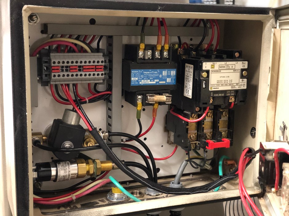
Finally, the control box needed to be sorted out. The original controls were removed from the machine by the previous shop for reasons unknown. The air switch was not functional and so the machine was running all the time when armed. In addition it was wired in a haphazard manner than while correct and operational was a bit of an ugly mess. A new air switch replaced the original, then the controls were organized using a DIN rail and wiring block.
This machine requires a chip blowout to keep the mortise clean as it works. Now I don’t have a huge compressor so I decided to add a solenoid to start and stop the air going though the chisel with the motor.
Here’s the function of the machine, I do a walk about and check prior to firing away. For these machines they must be armed (electric), air pressure must be right, dust collection on in my case and the port open, clamp positioned and cut depth set.
Most importantly, here is the result.

Thank you,
Brian